![]()
Der Durchbruch
Das Prinzip
Das Abroll-System
Das Zahnrad-System
Das Scheren-System
Das Stampfwerk
Soll ich mich schämen?
Die Software-Ratsche
autonom?
Impulsaustausch
Motus als Getriebe
Motus + Pendel
Motus + Satellit
Das Primum movens
Das Unwuchtsystem
Die Geheimnisse ..
Wenn ein Pfund ..
Das Kreuz
Der Drehpunkt
Das Kreuz im Rad
the momentous 13
my solution
the camshaft
geneva drive
... even more sites
in 2022
..back to startpage

© 2020 by Alois Zimmermann | Kontakt | Impressum | Updates | Ausblick |
The momentous 13 back to german
The previous pages dealt more with the system of Besslers big wheels. The first and smaller ones were built a bit simpler, in principle the same too, a wheel in a wheel, an unbalanced wheel in a wheel respectivly.
 |
The simpler solution of these wheels is better suited for explaining
Besslers ingenious invention. Simply stated, Besslers wheel is driven by
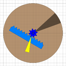
a wheel running continuously downwards inside, like already known picture
shows. Pivot point is left side of centre of gravity, so wheel tilts to
right side and rolls down. The following sequence of pictures will show, how this running downwards will be replaced by resonant swinging. One can imagine it like this: inner wheel runs down one tooth. By coupling at right rim, it will give off energy to outer wheel. This energy of outer wheel will be recovered to swing the inner wheel upward resonantly and then the process will start again. |
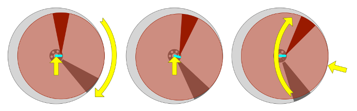 |
The wheel has rotated one tooth further, but the next tooth is then at the
same level as the previous was. And this can go on forever - a perpetual
motion according to Bessler.
Only by resonant energy exchange between inner and outer wheel this work
of the art becomes a self-running wheel.
In addition to the arrangement of the flying weights in the unbalanced system
the secret in the axle (gear with a torsion spring) makes an important part.
The weight and energy of the flying weights are repeatedly exchanged between
the two wheels. The secret in the axle makes the synchronisation.
Maybe Bessler meant this in his Apologic Poetry on page 88:
Stininess is a root of evil'
(it's not possible without the exchange of energy)
An anvil will get many knocks'.
(the anvil will appear immediatly on this site)
 |
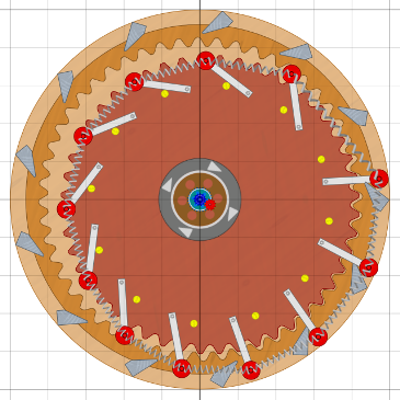 |
After MT137 was a topic at besslerwheel-forum, i designed an
unbalanced system with 12 flying weights with suitable ropes and
i integrated it right side shifted into the larger outer wheel.
Now the question arised: In which form should the energy exchange
take place?
Via the axle (gearbox) only or also on the rim?
Twelve anvils at the circumference (see picture above leftside), that
did not fit. The weights will not rest long enough.
How about 13? (right side)
That was it, great! Now they turn the outer wheel from 3 o'clock to
5 o'clock. Also the offset of the two wheel shafts is defined now, not to
big and not to small, right way. Immediately the Mayan wisdom came to
my mind:
„ ... the thirteen brings the motion!”
The number of teeth of the outer wheel should therefore be a multiple of 13. Now its clear why the woodcut of the Merseburg-wheel shows 117 mounting pins on the circumference: 117 = 13 x 9.
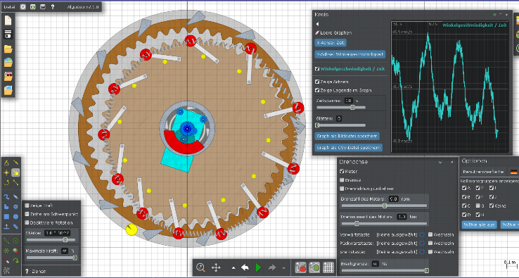
Of course there is an Algodoo scene for simulation and optimization too.
For me it runs best at about 7 rpm and then it needs less than one Watt
of motor power. In order to run at 40 rpm like Besslers first wheels did,
suitable torsion spring has to be installed and tuned to about 10 Hz.
I still have my problems with that. The point why the scene doesn't run
smoothly are the gears in the center in my opinion. I guess there is a
bug in Algodoo creating gears of a certain size.
Download the scene here
or by clicking on the picture.
When i look at the scene, i always
have an association to MT13, see also button Impulsaustausch.
There the 13 is even in the title of the picture.
I further searched, where Bessler might have hidden or coded the system
12:13 and i found MT55.
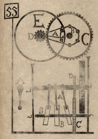 |
I have always wondered why the cogwheel on the upper right has 49
teeth. That's gotta mean something. Now I know. As we have seen above
the unbalanced wheel has 12 flying weights, but the outer wheel has
13 anvils. So a 12:13 transmission is necessary for the gearbox in the center too. And exactly this is shown in MT55. Left gear-wheel has 12 teeth, right gear-wheel has 4+9=13 teeth, coded as expected with Bessler. Other aspects point to this interpretation: - the two gear wheels are shown horizontally above - at the bottom the gear wheels are similar in size - the two gear wheels couple two shafts - there is an energy exchange between the shafts As you can see by this example, it doesn't make sense trying to read the construction of a Bessler-wheel out of his Maschinentractate. However it will help, if after much thinking and trying, own solutions are created, to find them in corresponding coded form in Besslers writings. |