... further steps
in 2022
... two and two
the first wheels
MT18, wheel in wheel
MT18 with two arms
MT18 with three arms
Sketch of wheel 1
AP wheel in 3D
back to next steps
back to startpage
| back to german |

© 2022 by Alois Zimmermann | Kontakt | Impressum | Updates | Ausblick |
... two and two
„They are now always two and two/
When one thing takes the outer place/
the other one drives to the shaft/”
... so writes Bessler in AP 81.
Now that the driving of the flying weights has been clarified in principle, next step is to work out the mechanics, especially the large gear ratio.
 |
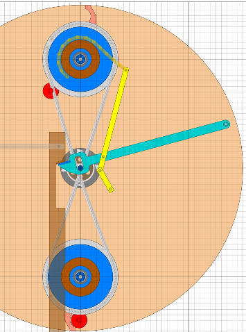
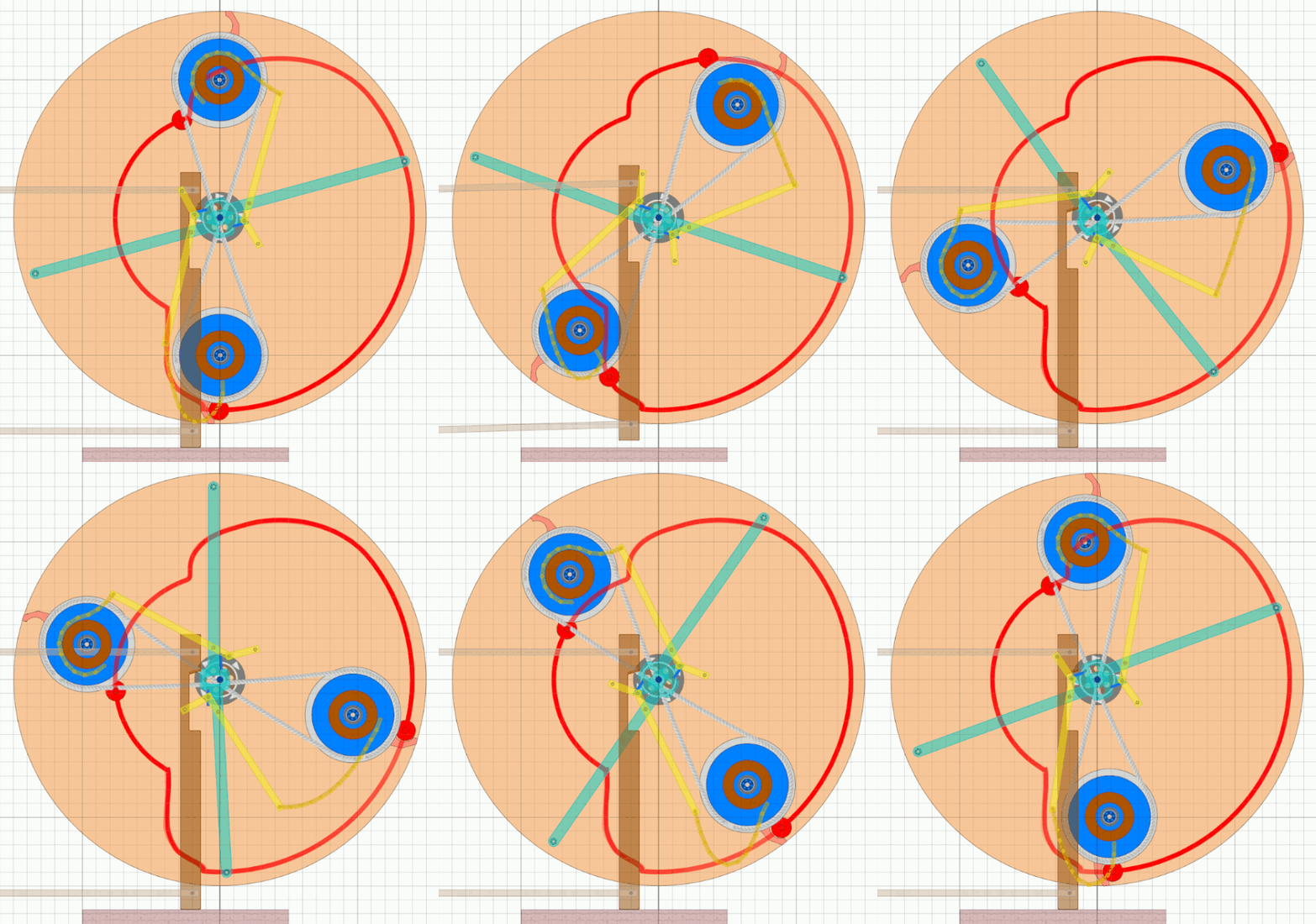
The transmission is done here by the yellow levers. The green lever can only move slightly in its oblong hole. In the picture the upper weight is inside and the yellow mechanism (lever and rope) holds the green lever up. When the stampfer engages, the green lever is pushed downwards, the yellow lever swivels to the right and so accelerates the flying weight outwards. The two yellow levers are in principle the economy version of a scissor mechanism. With the exception of the fulcrum previously named A all the forces have an accelerating effect on the wheel. Initially, both weights have to start moving and even be lifted. This is exactly where the stamper mechanism delivers the greatest force. In the middle of the swinging movement, the power requirement decreases. The lower weight accelerates due to pirouette effect and the upper becomes subject of centrifugal force. That’s the time when the stamper begins to lift. Then, however, the power requirement increases again, when the upper weight on the outside wants to slow down, but has to speed up. In this case the stamper remains active until the flying weight has reached its final position. |
As already known from earlier simulations, Algodoo has problems with such tasks.
The gif animation could only be created at very slow speed and minimised masses.
The Algodoo scene used for the animation can be downloaded
here.
 |
 |
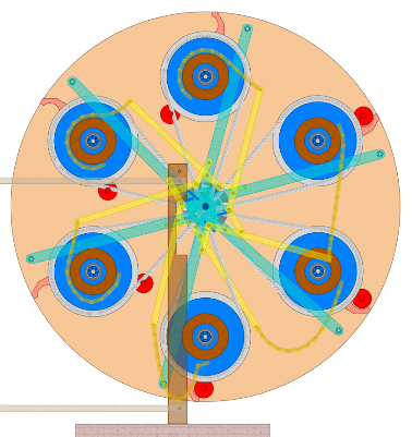
The first two wheels had three stampers and thus probably six flying weights. The weights at 6 o’clock and 12 o’clock here are before the swing in and swing out respectively. One can see that the weights at 2 o’clock and at 4 o’clock create an imbalance and thus a torque in the direction of rotation. According to previous considerations the force for swinging in and out comes for the most part from the reaction force when the stamper is lifted. The imbalance at 2 and 4 o’clock therefore only has to generate approx. 20 to 30 percent more torque than would be necessary for the pure stamper lifting. In principle, there is only an optimisation task and the arrangement of the control mechanism in the axle. |
The pin to lever mechanism in the axle looks more difficult at first than it actually is
when you approach it three-dimensionally.
You can even move the pivot point A into the axle in such a way that it no longer
generates any backward momentum - MT69 says hello.
It is therefore only necessary to find stiff and torsion-free materials,
and to place the hanging and pivot points at the right places.
With today’s technology this is certainly no problem,
but in Besslers time it was a challenge and an absolutely admirable achievement.